


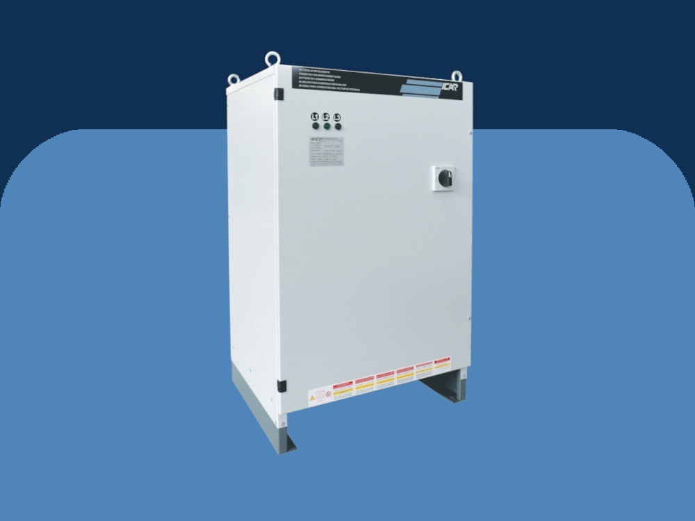
PFC - Power Factor Correction systems
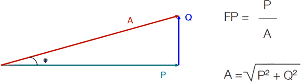
Electric installations are characterized by three kinds of power: active power (P) linked to the load resistive component, reactive power (Q) linked to the load inductive component and apparent power (A).
The mean value of the reactive power in a wave period is nil. Therefore, the reactive power does not contribute towards the generation of mechanical work and constitutes an additional load for the energy source, forcing it to oversize its generators and transmission/distribution lines.
The parameter that defines the absorption of inductive reactive power is called power factor (cosφ) and is represented by the ratio between active and apparent power.
Assuming there are no harmonics in the system, the power factor is equal to the cosine of the angle between the voltage vector and the current vector (cosφ). The power factor decreases when reactive power increases.
A system working with low power factor shows the following disadvantages:
- High power losses in transmission/distribution energy lines
- High voltage drop.
- Oversized design of generating, transporting, and transforming plants.
By installing a capacitor battery, it is possible to reduce the reactive power absorbed by the inductive loads connected thus increasing the power factor.
There are several ways to perform the power factor correction and the choice depends on daily load duty-cycle, load distribution and type of service.
The main choice is between distributed or centralized power factor correction.
If the correction system is distributed, the units are located in the vicinity of each load for which the power factor needs to be corrected.
The daily load duty-cycle is of critical importance when choosing the most suitable power factor correction system. Very often, not all the loads work at the same time and some are operative only for a few hours during the day. In this case, it is clear that the distributed configuration would be too expensive due to the high number of correction systems that would need to be installed and the idle time of several units.
Power Factor Correction (PFC) systems improve the power factor in order to prevent from problems, which resulted by the low factor.
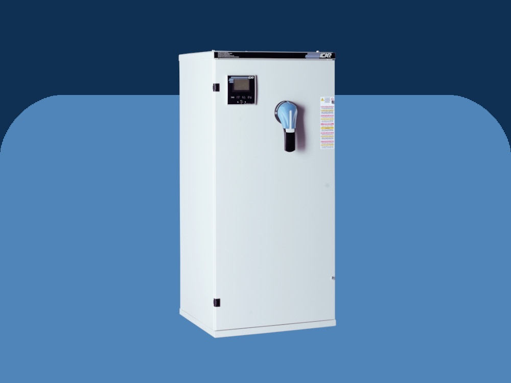
Capacitors
Inside ICAR automatic power factor correction systems, there is only three-phase polypropylene metalized high gradient capacitors resin filled (PCB free). The fundamental difference with respect to the standard polypropylene capacitors is how the dielectric film is metalized: if in the standard capacitors the metal layer thickness deposited on the polypropylene film surface is constant, for the «high gradient» ones the metal layer has a suitably modulated thickness.
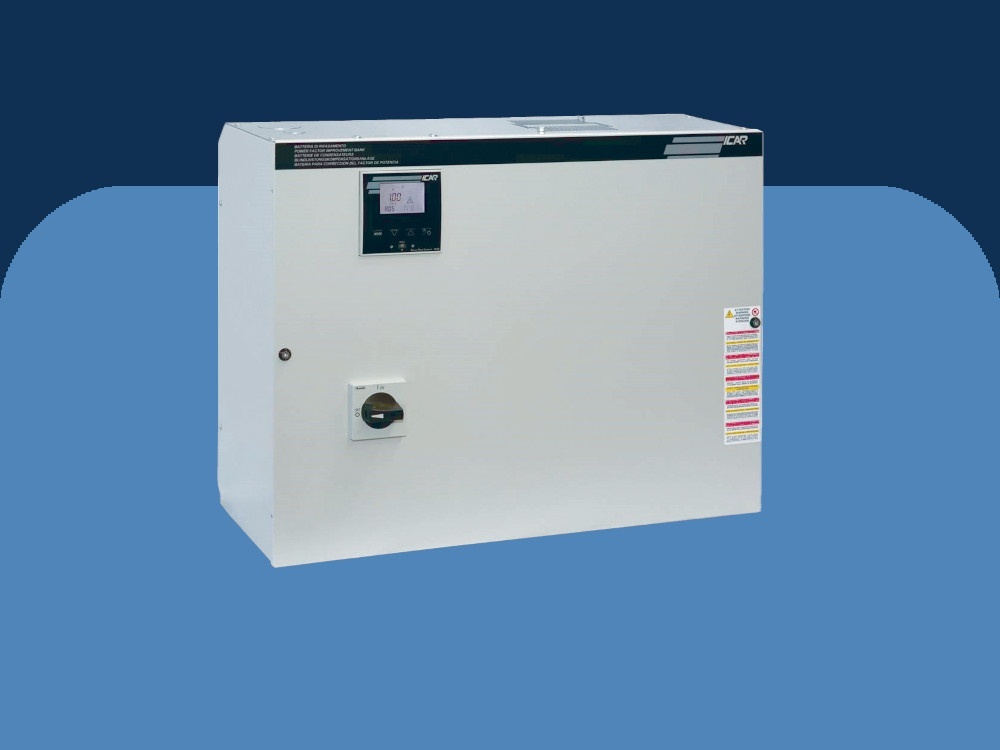
Reactive power regulators
The reactive power regulator, together with capacitors and reactors (in detuned filter cabinets) is, the key component of the automatic power factor correction system. It is actually the ‘intelligent’ element responsible for the verification of the power factor of the load, depending on which it controls the ON/OFF switching of the capacitors’ batteries. By doing so, the regulator maintains the system power factor above the minimum threshold set by the Energy Authority.
PFCs are manufactured for continuous operation at rated power from 100kVAr to 1000kVAr. The rated voltage is 415V and depending on the harmonics distortion of the circuit, the suitable type can be selected. PFC allows a continuous 1,3 overcurrent and 1,1 overvoltage. Also, there are allowed overload factors for capacitors, which are defined according to the selected type. In every capacitor a discharging appliance included.
The operational temperature of the system is defined as -5°/+40◦C and regarding the capacitors as -25°/+55◦C.
The applied manufacturing standards of the system are IEC61439-1/2, IEC61921 and of the capacitors is IEC 60831-1/2.
- Usually, in a plant with a low power factor, the payback of the installation costs is most likely achieved within a few years.
- Beyond the elimination of potential penalties from the energy bills, the technical and economical benefits deriving from the installation of a power factor correction system are listed below:
- decrease of the losses in lines and transformers due to the lower absorbed current
- decrease of line voltage drop
- optimization of the plant sizing. - Increase in power density (kvar/dm3) with a consequent power size reduction of the power factor correction systems
- Robustness against voltage surges, for greater reliability even in systems with the presence of voltage fluctuations due to the network or maneuvers on the system
- Improved behavior in relation to internal short circuit withstand.
- Minimized wear & tear of the banks of capacitors, due to the reactive power regulator
- Simple and intuitive installation and use of reactive power regulator
- Flexible modification of all parameters
- Power regulator special features for maintaining the PFC in order to identify and solve problems that could otherwise lead to damage and life expectancy reduction.
- In cases which the power factor of the grid is very low (with inductive loads like transformers, generators, etc) like industrial and marine grids, office buildings, malls, etc.
- Power factor correction systems indicated for the plants where the current harmonic distortion, without capacitors, installed has values higher/equal than 12% (grids with non-linear loads like inverters, welding machines, rectifiers, etc.


-91efcc9c.webp)


